
Measuring circumferential roughness on inside diameters of hard-to-reach spaces
Published on July 5, 2020
Last updated February 10, 2020
Our previous roughness measurement article presented a method for measuring linear (axial) roughness in hard-to-reach spaces such as tubes, bores, or narrow grooves.
But what if you need to measure roughness around the circumference of a hard-to-reach space? This capability is often required in the manufacture of high-precision parts where ID surface finish affects part performance.
Example
Sealing surfaces in the automotive or aerospace industries are prime examples. Take for instance the valve seat of an engine fuel injector. Excessive circumferential roughness on the valve seat ID will affect the seal, cause gas leakage, impact engine efficiency, and ultimately pose a serious risk to safety. Therefore, measuring and controlling roughness inside this component is non-negotiable.
Click on images for close-up view
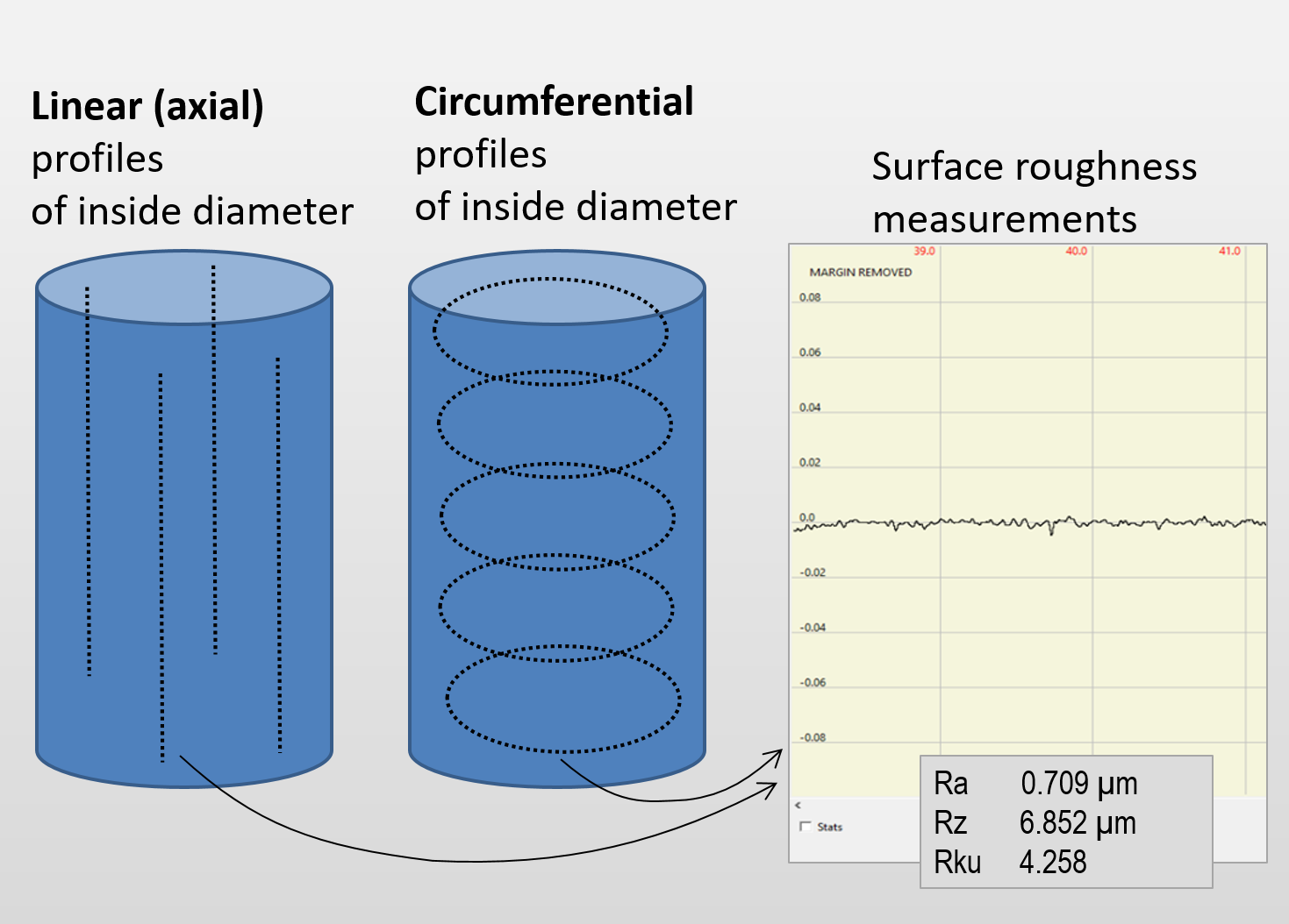
With Novacam non-contact 3D metrology systems, surface roughness measurements may be obtained on linear or circular profiles of inside diameters.
Let’s clarify – what do we mean by roughness?
The definition of what constitutes “roughness” as a surface quality parameter varies between sectors and companies. For circumferential roughness measurements, clients often use the term “roughness” to describe one or more of the following 4 surface quality aspects:
- Surface roughness. This is the most restrictive sense of the term “roughness”. It may be described as high-frequency / short-wavelength deviations from the nominal measured surface.

Surface roughness
- Surface waviness. Roughness and waviness are often found together but measured separately. Note that there is no universal size limit between waviness and roughness; rather the limit depends on the sector and type of application.

Surface waviness vs. roughness
- Surface defects on the ID circumference, such as scratches, corrosion, or pitting
- Chatter, meaning lobing that is typically created by vibrations between a machining tool (such as a CNC, grinder, mill, or drill) and a part during manufacture or finishing. (Learn more about chatter measurement here.)
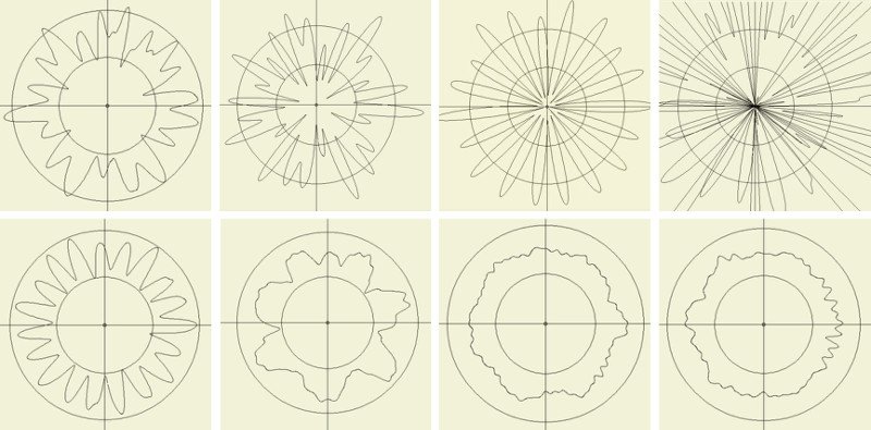
Examples of chatter analysis from ID of automotive shafts (measured and analyzed by Novacam 3D metrology systems)
Aspect #1, i.e., “surface roughness”, is the subject of this article.
However, let’s keep to the subject matter – from here on this article addresses surface roughness measurement only.
As an aside, note that regardless of the roughness definition, Novacam systems are able to measure all the above surface aspects -including roughness, waviness, dimensions, chatter, and defects. This is because all the necessary 3D profile data is acquired in the same scan. The acquired data points are combined to form a 3D point cloud from which all the above roughness aspects are easily analyzed.
Two systems for circumferential roughness
Novacam manufactures two non-contact 3D metrology systems that measure both axial and circumferential roughness on inside diameters:
- BOREINSPECT. The BOREINSPECT 3D metrology system scans IDs with a small-diameter rotational probe. The side-looking scanning probe traces linear, circular or spiral paths through the inside diameter (ID).
- The system offers both axial and circumferential roughness measurements.
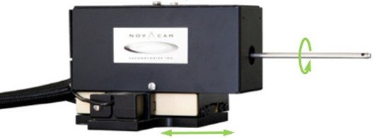
Novacam BOREINSPECT system scans ID surfaces with a rotational scanning probe
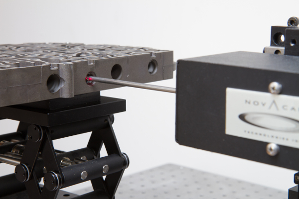
- TUBEINSPECT. The TUBEINSPECT 3D metrology system measures IDs by rotating the measured (typically tubular) part on a precision stage while a small-diameter side-looking scanning probe advances into the tube ID.
- Like the BoreInspect, the TubeInspect obtains linear, circular or spiral profiles of the ID.
- Additionally, the TubeInspect is able to measure axial and circumferential profiles on the outside (OD) of the same tubular part.
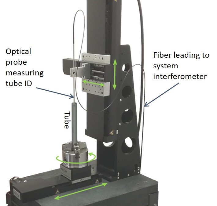
The TUBEINSPECT system rotates the measured (typically tubular) part to scan its ID and/or the OD.
Roughness parameters calculated from acquired profiles
The BOREINSPECT and TUBEINSPECT systems both acquire profiles in a point-by-point manner at the rate of up to 100,000 3D point measurements per second. The user chooses whether the scan paths are linear, circular or spiral.
The obtained data is used to calculate 2D roughness parameters such as average roughness (Ra), mean roughness depth (Rz), maximum valley depth (Rv), maximum peak height (Rp), maximum height (distance from highest peak to lowest valley)(Rt), root mean square roughness (Rq), skewness (Rsk), and kurtosis (Rku).
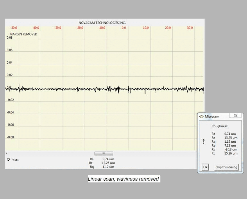
Example of 2D surface roughness measurements: Ra, Rz, Rq, Rp, Rv, Rt
Range of roughness measured
The BOREINSPECT and TUBEINSPECT systems measure ID roughness as small as 0.05 μm (2.0 μin). To acquire this very fine roughness, it is important to:
- Configure the system with MICROCAM-3D interferometer,
- Select a probe with sufficiently small spot size,
- Set the rotation speed of the probe (in the case of BOREINSPECT) or the tubular part (in the case of TUBEINSPECT) to be slower than for acquiring dimensional measurements.
For measuring higher roughness values, the above guidelines may be relaxed.
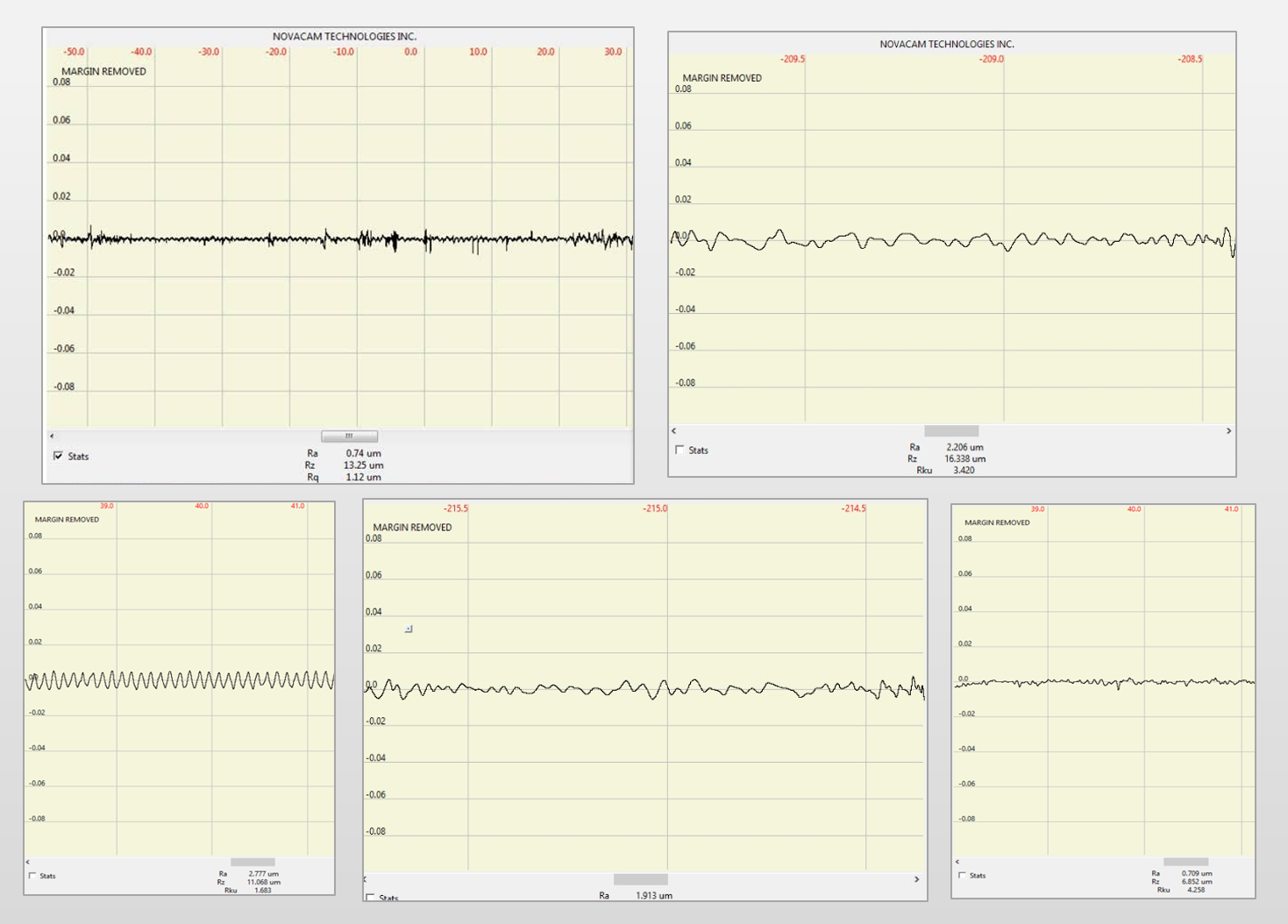
Examples of roughness measurement profile. Surface form and waviness has been filtered out.
Benefits to manufacturers
The systems offer many benefits:
- Micron-precision non-contact measurements
- Ability to measure roughness, dimensions, chatter and defects on the ID – all with the same probe
- Linear, circular or spiral profiles of the ID
- Support for full automation of measurements and reporting
- Faster acquisition than with contact probes or with manual inspection techniques such as use of replicas
- Better measurement coverage of high-aspect-ratio features (e.g. corners of O-ring grooves, undercuts, steps, channels, cross-holes, splines, threads) than triangulation technology or contact profilometers thanks to collinear scanning (see diagram)
- Suitability for both lab and shop-floor environments
- Option to integrate with robots, precision stages, or online inspection stations.
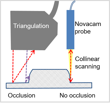
Novacam optical probes scan in a collinear manner, meaning that the outgoing and reflected beam travels along the same axis. This means that for scanning high-aspect-ratio features, there is no or minimal occlusion of corners compared to scanning with triangulation technologies.
Wide range of applications
The BOREINSPECT and TUBEINSPECT systems measure roughness on IDs of:
- Automotive power-train components
- Bearings
- Aircraft engine manifolds
- Gun drilled relief valve bores (oil & gas sector)
- Medical devices
- Barrels
- etc.
BOREINSPECT 3D metrology system rotational probe scanning inside bores in an automotive valve body
Which system is appropriate for my ID roughness application?
Both the BOREINSPECT and TUBEINSPECT are off-the-shelf 3D metrology systems that come equipped with an optical probe selected for the application.
When choosing between the two systems, here are some general points of consideration:
- Only the TUBEINSPECT can measure both the ID and OD of tubular parts
- Only the BOREINSPECT rotational scanner probe can be used as a robot end-effector; but both systems can have robots present the measured parts to them
- If the part measured cannot be placed on a rotational stage, then BOREINSPECT is the answer.
To ensure the best setup, parameters such as component size, weight, location, etc. need to be evaluated. Novacam application specialists are available to help clients determine the optimal configuration for your measurement application.
Learn more
Do you need to measure roughness inside hard-to-reach spaces?
Related links
See related products
Read related blog article:
See related applications: