3D metrology for EDM and laser machining
Measuring System: NOVACAMTM SURFACEINSPECTTM or EDGEINSPECTTM system
Keywords: micro-machining, electrical discharge machining, wire EDM, die-sinking EDM, laser machining, holes, slots, cavities
Tight tolerances and automation demands in micro-machining
In high-precision machining operations, workpieces shaped with electrical discharge machining (EDM) or by laser cutting must be verified against strict specifications. As precision demands grow, so too grows the need to improve our capability in measuring the dimensional and finish characteristics of the machined workpieces.
Additionally, in many high-precision machine shops, rapid and automated 3D metrology is now essential, and in-process inspection is increasingly the norm.
Limitations of contact CMMs and manual gauges
Inspection of micro-machined features with commonly used contact coordinate measuring machines (CMMs) or manual gauges, such as pin or plug gauges, presents the following limitations:
- The inspection is slow and/or labour intensive, and therefore often only a percentage of workpieces is inspected
- Many narrow EDM or laser-machined cavities are difficult or impossible to reach into with physical contact touch probes or with microscope-type gauges
- Often, defects are not detected immediately, affecting the production cycle. When inspection takes place in an area separate from the micro-machining station, any required correction impacts the production cycle more significantly than if the inspection were to be integrated right in or next to the micro-machining station.
- Problems with machining tools may not be detected quickly enough to prevent unnecessary defect propagation. For example, any damage of graphite electrodes in die-sinking EDM should be addressed immediately so as to prevent machining defects in the first place.
Non-contact inspection with SURFACEINSPECT system
In contrast to the above limitations of contact methods, NOVACAM SURFACEINSPECT non-contact 3D metrology system provides machining operations with an option to boost quality control and therefore productivity. Acquiring measurements at high speed and without affecting the surface, the SURFACEINSPECT system enables complete and automated quality control of machined workpieces.
Quick introduction –the SURFACEINSPECT system
- Provides non-contact micron-precision measurements of surfaces
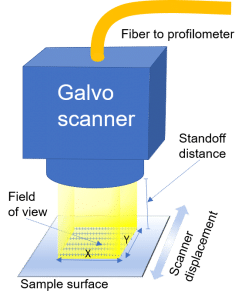
- Measures optically in a point-by-point manner and in a raster pattern (see diagram)
- Acquires surfaces at up to 100,000 3D-point measurements per second
- Is able to captures 3D data for calculating dimensions (GD&T parameters), roughness, and defects in the same scanning sequence.
Owing to the modularity and fiber-based character of its design, the SURFACEINSPECT system also provides versatility of installation that is unique in the industry (more on this later).
Measuring EDM-machined seal slots
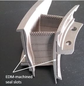
As part of a jet engine turbine, the stator blade (shown on the right) features EDM-machined seal slots that are approximately 30 mm long, 0.4 mm wide, and 1.8 mm deep.
Depending on the type of measurements required for a feature – whether geometry, roughness, defects, or thickness in case of a semi-transparent material – the user may configure the SURFACEINSPECT system acquisition parameters in terms of scanning path, speed, and density of acquisition. Geometric dimensioning and tolerancing (GD&T) inspections typically require the least amount of time and points, while long, higher-density scans may be required for linear or area roughness measurements or automated defect detection.
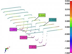
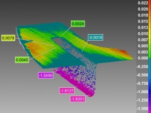
For illustration purposes, one of the blind slots on the pictured stator blade was scanned twice, each time with different scan parameters:
| Scan | Profile density | Total # of profiles | # of points per profile | Total # of points | Elapsed time |
|---|---|---|---|---|---|
| #1 | every 1 mm | 30 | 400 | 12,000 | 1.5 s |
| #2 | every 10 µm | 3,000 | 400 | 1,200,000 | 33 s |
As shown in the table above, the faster, lower-density scan provided 12,000 3D points, while the slower, higher-density scan provided 1,200,000 3D points as basis for surface analysis.
10-mm long sections of the two scans are shown below as micron-precision deviation maps.
Superior measurement capabilities, including tool condition diagnosis
In contrast to the contact measurement approaches above, the SURFACEINSPECT system:
- Offers sampling speed that is thousands of times higher than that of contact CMMs. Consequently, GD&T inspection cycle for machined surfaces is typically 2 to 4 times shorter, while the acquired data density is much higher
- Automatically captures three data formats – 3D point cloud, height images and intensity images in the same scan (examples shown on the right). Combined, these three data formats facilitate rapid defect detection on machined workpieces
- Is able to scan high-aspect-ratio features such as interiors of very narrow machined cavities (slots, holes, etc.)
- Can be integrated right into or next to the machining station, and thus enables quick feedback on workpiece dimensions. This translates into lowered cost of defect correction (see Versatility of deployment below)
- Helps diagnose tool problems quickly, preventing error propagation.
Tool quality checking can be done in two ways. When the scanner is integrated right in the process, even small-magnitude non-conformities on measured workpiece surfaces can indicate problems with the tool; alternately, the tool tips (e.g. graphite electrodes in die-sinking EDM) can be scanned directly for signs of damage (cracking, etc.) to diagnose the need for dressing or changing the tool tip.
Choice of automated or in-lab inspection with the same instrument
With the SURFACEINSPECT, automation of inspection is fully supported by system capabilities such as datum alignment, automated pass/fail reporting, and exportable reports. Acquired point clouds may be evaluated with respect to user-defined criteria (GD&T, linear roughness, surface roughness, and defect detection), or compared to a reference CAD model.
For in-lab inspection, accompanying metrology software on a PC (e.g., InnovMetrics PolyWorks InspectorTM) enables full viewing and analysis of the acquired point cloud as a 3D interactive map. Views such as deviation maps provide key insight into micro-machining processes.
Versatility of deployment
The SURFACEINSPECT system, like all NOVACAM 3D metrology systems, uses low-coherence interferometry (LCI) technology. It is also a fiber-based modular system, meaning that its galvo scanner probe is connected to a single signal-processing detector box (interferometer) with an optical fiber that can be several meters long. As such, the fiber-based probe:
- Can be mounted on inspection stages and angled to suit the majority of workpiece features
- Is easily integrated as either a robot arm end-effector or as a 3D vision component in automated or semi-automated systems on the plant floor
- Provides the versatility and latitude needed to acquire almost any geometry in a single scanning sequence—no need for composite imagery.
See a more complete list of advantages of our fiber-based LCI systems.
Related links
Download application note “3D Metrology for EDM and Laser Machining” [4 pages, PDF, 1 MB] for more details on this application
See related applications:
- Cooling holes inspection (EDM or laser-machined features)
- Roughness measurement
- … and more
Contact us or request free sample analysis to see if the SURFACEINSPET system is suitable for your precision machining application
