Edge radius measurement
Measuring System: NOVACAMTM EDGEINSPECTTM system
Keywords: edge break, edge radius, sharpness, cutting edge, cutting tool geometry, blade edge, leading edge, trailing edge
The quest for the perfect edge
Edge finishing processes are a crucial component of manufacturer guarantees. Whether it is for deburring or deflashing, or conversely ensuring edge sharpness, having a solid quality assurance edge inspection method can add tremendous value to a product.
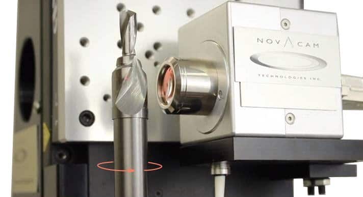
NOVACAMTM EDGEINSPECTTM 3D metrology system measures edges in a raster pattern, at high speed (up to 100,000 3D-point measurements per second), with sub-micron precision, and in a non-contact manner. The system provides 3D characterization of:
- Edges on machining tools tools: high-precision reamers, drills (PCB, PDC, PCD, etc.), thread mills, boring bars, cutters, etc.
- All types of edges: round holes, straight edges, cross holes, inside or outside edges
- Any number of edge specifications: edge break requirements, angle measurements, as well as matching edge radiuses or checking tolerances after burr removal
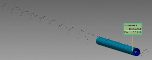
- Very sharp cutting tools: scalpels or razor blade edges (see image below)
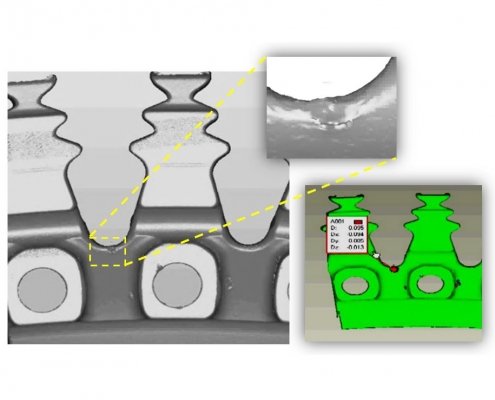
- Defects on edges: e.g., burrs or deviations such as undercuts or passing. See below example of chamfers defects on fir-tree bases of jet engine turbines.
With the EDGEINSPECT system, all geometry and roughness data on edges is captured down to the micrometer. Defects such as cracks, scratches, dings, or pits the user deems important may be detected and measured automatically based on user-defined dimensions and tolerances.
Measurement of cutting tool edges
To help ensure edge sharpness, the EDGEINSPECT system verifies that the cutting edge of machining tools is as per requirements—either at the manufacturing stage, during routine inspection, or during tool reconditioning.
Characterization of the edge and any defects and visualization of the acquired data is made easy with the EDGEINSPECT system. The 3D point cloud acquired by the system is fed to the accompanying metrology software (e.g. InnovMetric PolyWorks InspectorTM) on a PC. From there, several data viewing options are available, including:
- 3D models
- Comparison to CAD model
- Deviation maps
- Exportable reports.
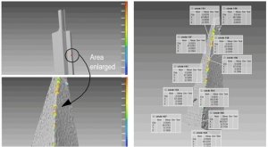
Users can zoom from an on-screen rendering of the acquired drill bit (top left) into the edge area selected for analysis. The enlarged edge segment (bottom left) shows a colour-coded deviation map of the edge sharpness. Users may choose to view edge radii measurements at various points of analysis (right).
Razor blade sharpness measurement
This 3D point cloud generated for a razor blade characterizes an edge radius of less than 6 µm (222 µin.). As shown, a cylinder fitted within the points acquired at the edge gives a micron-precision breaking-edge diameter measurement.
Defect inspection on a fir-tree base of a jet engine turbine disk
A fir-tree base of a jet engine turbine was measured to assess the edge’s conformity to specifications. On this part, a chamfer defect was detected, measured and flagged.
Automated or in-lab inspection
Automation of edge metrology is fully supported by the EDGEINSPECT system capabilities such as datum alignment, automated pass/fail reporting, and exportable reports. Edge break data may be evaluated with respect to user-defined criteria (GD&T, sharpness, surface roughness, and detection of defects), or compared to a reference CAD model. For in-lab inspection, accompanying metrology software on a PC enables full viewing and analysis of the acquired point cloud as a 3D interactive map. Views such as deviation maps provide key insight into edge machining and finishing processes.
Advantages of measuring with a fiber-based metrology system
The EDGEINSPECT system, like all NOVACAM 3D metrology systems, uses low-coherence interferometry (LCI) technology along with fiber-based modular design. As such, the scanning component of the EDGEINSPECT system – the galvo (raster scanning) probe –
- is connected to the system’s signal processing detector (low-coherence interferometer) via an optical fiber that can be several meters long
- can be mounted on inspection stages and angled to suit the majority of edge features
- is easily integrated as either a robot arm end-effector or as a 3D vision component in automated or semi-automated systems on the plant floor
- provides the versatility and latitude needed to acquire almost any geometry in a single scanning sequence—no need for composite imagery.
See a more complete list of advantages of our fiber-based LCI systems.
Related links
Download application note “Inspecting Edge Breaks / Edge Radius” [4 pages, PDF, 0.8 MB] for more details on edge measurement applications
Watch related video:
Contact us or request free sample analysis to see if the EDGEINSPECT system is suitable for your application.
